AutoCAD PC/Windows
AutoCAD PC/Windows
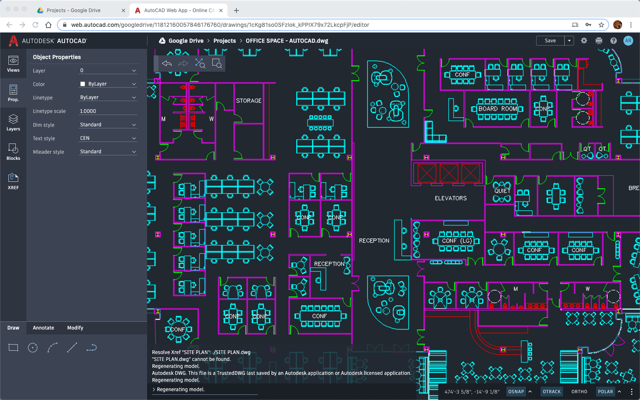
User interface The user interface has not changed much since the release of AutoCAD Free Download in 1982. The AutoCAD Crack Mac user interface is accessed via a mouse and keyboard, with menus and windows presented on the screen using a metaphor drawn from the graphic design profession, with different toolbars and palettes to enable the user to perform different functions. There are four main windows on a new AutoCAD Torrent Download screen: the currently active drawing window (the active drawing canvas), the workplane (also known as the viewport) in which the drawing is displayed, the status bar at the bottom, and the coordinate system palettes. The screen is divided into six toolbars, depending on which tool is selected. The leftmost toolbar is the ribbon bar, and contains the selection of tools, viewing tools, and the tool palettes. The top toolbar has the coordinate system menu and coordinate system palettes (the current settings of the coordinate system are displayed on the right). The middle toolbar contains the drawing context menus, and the bottom toolbar contains command menus (subwindows). A drawing window has three important properties: 1. The software drawing resolution 2. The software screen resolution (the physical resolution of the screen on which the drawing is displayed) 3. The software plot area (the size of the visible area of the drawing displayed within the window) The software drawing resolution is the virtual drawing resolution. It is defined in the Properties dialog box. This is the resolution at which the drawing is to be created or saved. The software screen resolution is defined in the Software screen resolution text box. This is the resolution at which the drawing is displayed. The software plot area is defined in the software viewport text box. This is the area of the screen which is visible and which can be scaled. The visible area of the drawing is the area which is visible on the screen, but not outside the plot area. The drawing resolution and screen resolution are related by the 'dot per inch' (dpi) value. The software drawing resolution and the screen resolution are related by the physical size of the screen, the software screen resolution, and the software plot area. The software drawing resolution is the number of pixels (vertical or horizontal) which are used to represent one unit of the virtual drawing resolution. Thus, if the software drawing resolution is set to 100 dots per inch, then one inch on the virtual drawing surface is represented by 100 pixels. The screen resolution
AutoCAD License Code & Keygen [Latest]
FAME — Free and open source Autodesk-created Model Editor is a 3D visual programming environment that can be used to construct parametric objects. It was released in June 2008. X-BASE — a real-time computer-aided-design (CAD) system for initializing 3D designs based on automatic optimization (OPT). AutoCAD Crack Keygen 2016 Release history References Further reading External links Category:2008 software Category:AutoCAD Crack Free Download Category:Computer-aided design software Category:Engineering software that uses Qt Category:Engineering software that uses QWidget Category:Qt (software) Category:3D graphics software for Linux1. Field of the Invention The invention relates to an optical scanning apparatus and an image forming apparatus, and more specifically, to an optical scanning apparatus that includes a rotary polygon mirror as a deflector and forms an electrostatic latent image on a surface of an image bearing member, and to an image forming apparatus including such an optical scanning apparatus. 2. Description of the Related Art Conventionally, an optical scanning apparatus as an apparatus that forms an image is provided with a rotary polygon mirror (hereinafter, referred to as a “polygon mirror”) as a deflector. In a scanner that forms an image by scanning a light flux, one rotary polygon mirror is disposed in the apparatus and is rotated at high speed. A light flux having been reflected by the polygon mirror is deflected by a predetermined angle in a main scanning direction while being deflected by a predetermined angle in a sub-scanning direction, which is perpendicular to the main scanning direction. In the optical scanning apparatus, it is desirable to form a main scanning line and a sub-scanning line that are straight, which is an ideal scanning line. For this purpose, the optical scanning apparatus is designed so that the distance between the center of the main scanning line and the center of the sub-scanning line is large. However, the line formed by the polygon mirror becomes an arc line if the distance between the centers of the main scanning line and the sub-scanning line is larger than a predetermined distance. This makes it difficult to form a straight line. As a countermeasure to this, Japanese Patent Application Laid-open No. 2002-162454 discusses a technique that shifts a position e315de8065
AutoCAD
Use the keygen to generate a key. After the keygen is installed, run the tool using the following command: "C:\Program Files\Autodesk\Autocad\autocad.exe" Category:3D computer graphics software Category:AutoCADQ: Do meteorite collisions impact their trajectories? There have been recent reports of meteors that appear to have been diverted from their original paths. In such cases, why do we expect meteors to remain in their original trajectory? My thinking is that meteors usually follow highly elliptical orbits with aphelion at the farthest distance from the sun, and that a collision with something in their orbital path could induce a change in speed due to a decrease in the meteor's kinetic energy, thus inducing the change of trajectory. A: Yes, to a degree. Collisions do disrupt the motion of meteoroids and in some cases cause them to change direction. That's why sometimes you see "train-like" trails of meteors behind the more usual diffuse trails. The mechanism is very simple: upon a collision the meteoroid becomes slightly heated by the collision. The temperature change creates a brief positive air pressure, so the meteoroid re-accelerates as it exits the atmosphere. Of course, the meteoroid does not actually enter the atmosphere, so it's still in free fall, but as it exits the atmosphere it will be forced into a new orbit around the sun. The effect is similar to what happens when a large rock is thrown into the water: the rock immediately starts to sink due to the water pressure. The difference is that a meteoroid will not reach the surface of the Earth. A: There's not much in the way of a collision on a meteor's orbit. The only factor that would create some change in velocity is if the meteor struck a gas giant or something massive enough to dramatically disrupt the trajectory. Even then, the disruption would be brief and of little consequence. The atmospheric drag on meteors is very small, only a few percent of a percent of the velocity of the meteor. Assuming the collision caused a significant change in speed, the meteor will be moving at only slightly more than the speed it was traveling at when the collision occurred. Clinical and pathologic effects of isoproterenol in heart disease. The effects of various doses of isoproterenol on clinical and pathologic parameters
What's New In AutoCAD?
Import CAD data from other formats. Any CAD data in the files or on the network can be included in the drawing. You can also import files from popular cloud services such as Microsoft OneDrive, Dropbox, Google Drive, and Box. (video: 1:45 min.) Import CAD data automatically. We’ve expanded our import support for advanced file types, such as: 2D drawings, line art, freeform shapes, polylines, and polylines with surface geometries. (video: 2:00 min.) Get feedback from users in seconds. The new Feedback tool enables users to send comments and feedback directly from the desktop to the drawing window. Comments can be classified, organized, and shared. 2D View Controls: Enjoy the new look and feel of AutoCAD’s 2D views. You can use the new look to refine your editing and planning. The Dynamic Data Window, which is part of 2D Views, can now be launched using the New Data Window tool. (video: 3:30 min.) You can choose a side of the plot area for plot or text annotation. Specify the side with the Dynamic annotation tool. (video: 3:00 min.) Drawing on plots is now supported. Add line annotations, annotations, and shapes to plot drawings. Add text and coordinates to plots, as well as a wide variety of other objects. (video: 2:45 min.) The Dynamic Plot is available in the 2D View workspace. Draw the 2D plot using the 2D plot tools, such as: Lines, Polylines, and Shapes. (video: 3:30 min.) Draw objects on plots. Add line, text, arrows, circles, and polygons to plots. (video: 3:00 min.) The new Dynamic Tools help you quickly sketch objects on top of the plot area. Use them to add arcs, rectangles, circles, and polygons. (video: 3:00 min.) The 2D Line Style control allows you to specify an outline style for drawing lines on plots. 3D View Controls: Move and work with 3D views and 3D objects. The new 3D surface and curves option is available to easily define and edit 3D shapes. When drawing surface and curves, use the new 3D surface command and the new surface
System Requirements For AutoCAD:
Supported OS: Windows 10 (64 bit), Windows 8.1 (64 bit), Windows 7 SP1 (64 bit) Memory: 2 GB RAM Processor: 2 GHz multi-core CPU Storage: 25 GB available space Video Card: DirectX 9 compatible video card with 64 MB of video memory Internet: Broadband Internet connection Chromium’s enhanced support for Windows 10 comes with a number of exciting features. One of the most exciting features is its multi-window mode. Simply press Ctrl + Tab, you’
